
Water Softener Installation
Water Softener Installation
ALL SHORTAGES OR MISSING PARTS MUST BE REPORTED WITHIN 24 HOURS OF RECEIVING ORDER. WE WILL REPLACE ALL MISSING PARTS BUT PLEASE BE REASONABLE AND REPORT IN A TIMELY MANNER.
Attention Customers: If you are hiring an installer, it would be in your best interest to assemble all equipment before their arrival. This will reduce the amount of the time they will have to spend at your home, potentially saving you hundreds of dollars in installation fees. In most cases installers prefer to have all “prep” work done to the equipment prior to their arrival.
PLEASE NOTE: We strongly recommend that you install a testing port (spigot or faucet) before and after each piece of filter equipment. It’s always good to be able to test the water going into and coming out of each filter.
Please read ALL instructions before attempting assembly.
Water Softener Components
- Mineral Tank
- Riser Tube (contained inside the tank)
- Brine Tank ( Salt tank) your softener may include salt rack
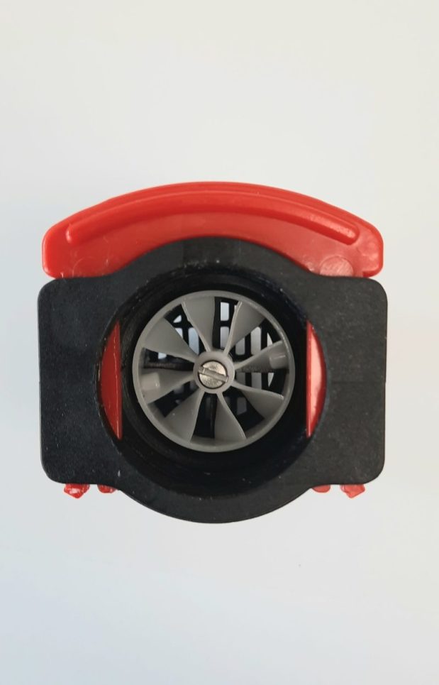
- Control Head (Control Valve) NOTE: S-100 control valves should be in metered mode with a FAN symbol on the screen. If there is a clock symbol displayed push the button with the FAN/CLOCK symbol and be sure the FAN is displayed.
- 12v Transformer
- Drain Elbow (Attached to control valve)
- Brine line
- Bypass valve (if purchased)
- Cation Resin (Golden in color, feels like wet sand)
- Gravel
- Upper basket
- Lower basket (this should already be attached to riser tube but be sure it is)
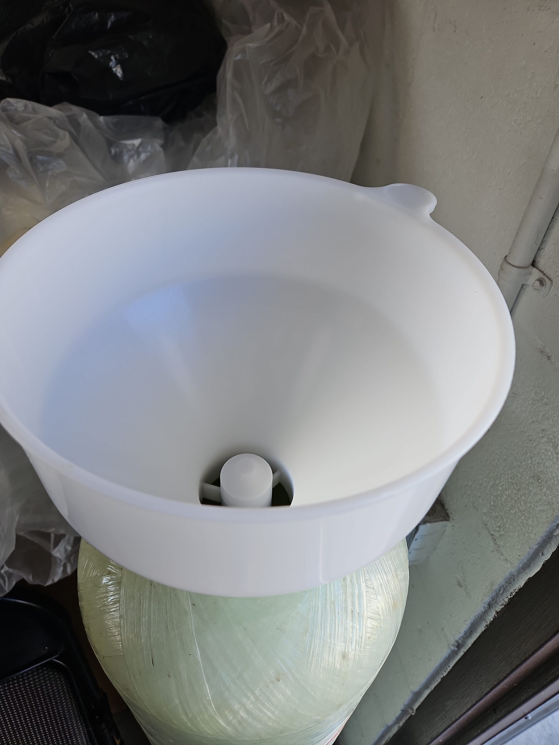
- Funnel (for pouring of Resin into tank)
- For tanks larger than 14″ diameter (105K and up)–Hub and laterals
- Two male threaded Tail Pieces (Important, On the S100 control heads one of the tail pieces has an impeller installed inside. That tail piece must be installed on the incoming water side of the control head. There is a sensor wire attached to the control head that plugs into a receptacle on that tail piece.)
Resin Amount Breakdown
| Softener Size | # of Boxes | Capacity (cu ft) |
|---|---|---|
| 30k | 1 box | 1.0 |
| 45K | 1 box and partial bag .50 cu ft | 1.50 |
| 60k | 2 boxes | 2.00 |
| 75k | 2 boxes and partial bag .50 cu ft | 2.50 |
| 105k | 3 boxes | 3.00 |
Setting Up the Water Softener
Step 1
Make sure the riser tube, also known as distributor tube, is centered. There’s a bevel at the bottom of the mineral tank. Make sure there is a basket on the bottom end of the riser tube. You should have been sent a white funnel that covers the riser tube for you, but if not make sure the top of the riser tube is covered while filling the tank with resin. (a plastic bag with rubber band works great) there may be a cap on the top of the tube. Uncover the tube once the tank is filled with all the resin. It is VERY IMPORTANT that you do not get any resin Inside the riser tube.
PLEASE NOTE: For larger size softeners, 105K or more, you must assemble the hub inside of the tank. Your riser tube will fit into this.
Fill the resin tank
First, pour the Gravel into the tank. Then pour the Resin into the tank. Make sure you pour all of the resin in the tank. Once you pour all of the resin inside the tank, fill the tank with water and let it overflow a little so that you ensure the air is out.
A good idea would be to tap or gently kick the tank to push bubbles up from the tank. If it all possible use the riser tube to push the water into the tank. That is also a good way to avoid air being trapped inside the tank.
Resin Colors


Step 2
Put on Upper Basket
Follow the below pictures and attach the upper basket to the bottom of the control head. The upper basket will slide through the riser tube.
Before you screw it on turn valve over and make sure the O-Ring in the bottom of the control valve that seals the top of the tank with the control valve is still in place. Sometimes they fall out and into the box they came in. You should not throw any boxes or wrapping away until you are COMPLETELY finished with your installation.
Step 3
Mount Control Head (Control Valve) on to Tank
You are almost finished assembling the softener, just hand tightened the control valve onto the tank, make sure the O-ring is on straight at the bottom of the control valve.
Step 4
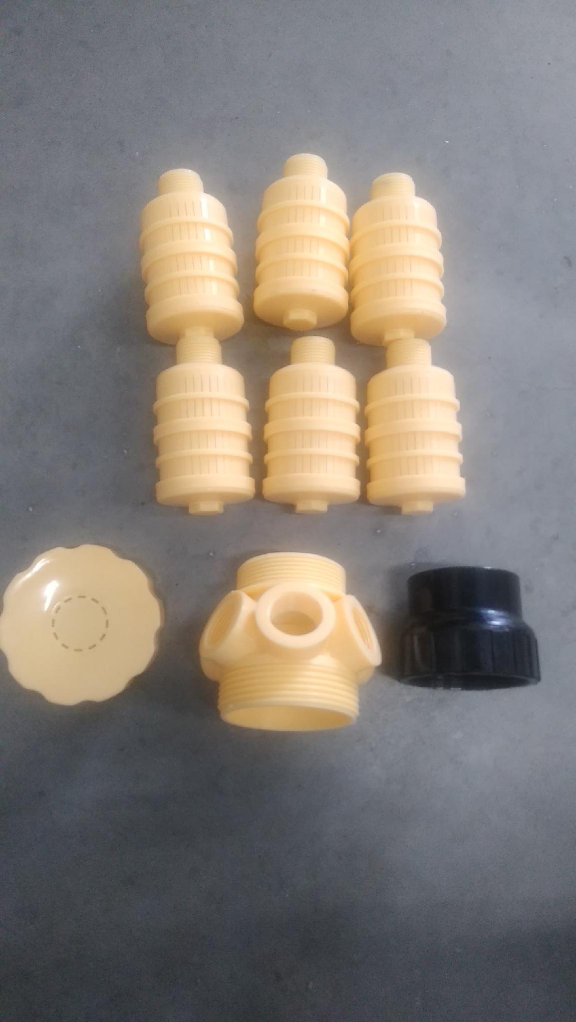
Assemble the Brine Tank Fittings
Parts needed here: Brine tank line, fittings for brine line come in different configurations some have threaded fittings, and some have compression fittings for threaded elbow at brine tank and at the brine connection on the control head.
Brine Tank Line
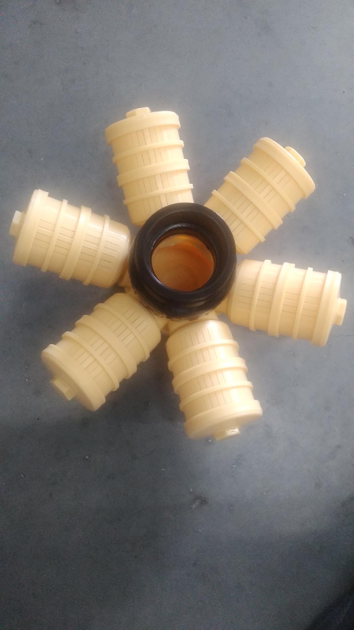
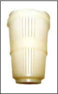
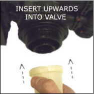
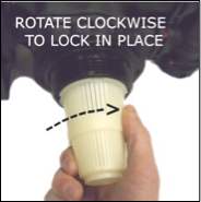
The brine tank line (or salt tank line) runs between the brine tank and the control valve of the conditioner. There is a little insert that goes on both the control valve end of the line and the brine pick-up assembly. It usually comes inside the connection points held in place by a nut cap used to secure the brine hose to the connection points. One in the injector connection point on the conditioner, and the other in the connection point on the top elbow of the pick-up assembly in the brine tank. Slide the nut cap over the brine hose, then place the insert into the ends of the brine hose and attach to the connection points at the softener and the pick-up assembly in the brine tank. The insert and the nut cap will cause a compression fitting.
There is a salt rack that goes into the brine tank. The salt rack has cups (legs) that attach to the bottom of it and then the rack is pushed down to where those cups touch the bottom of the brine tank.
Step 5
Plumb the Softener
NOTE: After you have completed assembling the Brine tank, it will need water put in the brine tank you need 4 gallons of water.
Find the main water supply line. If you’re not sure how to do that follow the instructions here.
You are now completely assembled and ready to plumb the softener in. Please follow the arrows on the valve for the inlet and outlet. The drain line requires 5/8” tubing. Flex tubing is recommended, especially the clear tubing. Be sure to use tubing that has walls thick enough that it will not easily kink or collapse. The drain line should be air gapped. It is not recommended that you install the drain line going up. The 5/8” line should be used for those running to drain no longer than 15 ft. If you are going to go longer then 15 ft then you do not install the drain elbow. You simply attach a 3/4” adapter and use 3/4” hose to that. The thread on the middle of the valve is universal. We do not make any equipment proprietary. If you must, tap into the drain line on a rafter.
Please follow the following directions
- Do not go higher then 3 ft straight up.
- Once you have tapped into the pipe to drain into, install a 45 degree elbow to tie the softener drain line to act as air gap.
- Do not tie 2 drain lines together.
- Do not use “hard” pipe. Use flex hose for drain lines. Hard plumbing means using PVC or copper lines straight out of the backwash port on the back of the valve.
For those with PEX piping, the softener should be installed prior to the PEX manifold.
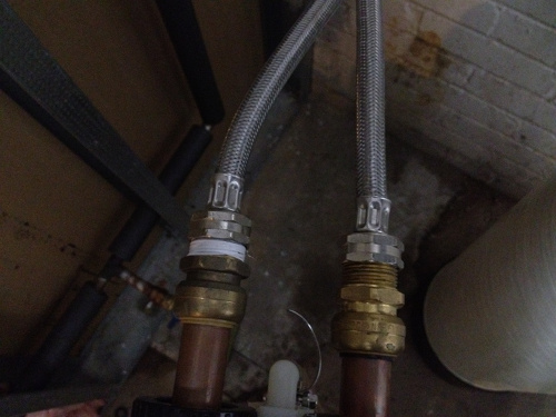
The use of “Gator” or “Shark” bites are a much better option for the do it yourself customer. They use very little sweating or gluing of pipe and they do not use many elbows that cause pressure drop if any at all. Below are a couple pictures showing what we mean.
Picture shows connections from the back of the softener copper tail pieces and stainless steel braided hoses connected to it. Very simple to do and it saves time.
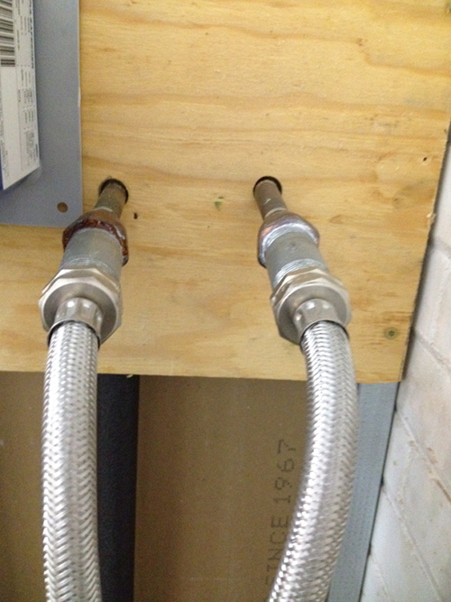
This pictures is the incoming pipe which connects into softener then goes back out.
Control valves are pre-programmed before they leave the warehouse. If you have any questions about the programming call our tech support number 412-828-6003 and we can help you over the phone.
Or you can email them at techsupport.waterfiltersofamerica.com
Note: Call tech support at: 412-828-6003. If you are interested in contacting our tech support on a weekend or if you need immediate tech support because you have an emergency, call the main number for the company that sold you your equipment.